Lines and linking
Lines are the connectors of a diagram. A line (TTMSFNCBloxLine) draws a path
between two points and, in most diagrams, anchors those points to block link
points so the connection follows the blocks as they move. This chapter covers
creating and anchoring lines, choosing a line style, configuring arrows, forcing
connections, and labelling a line.
Connecting two blocks
To connect blocks, create a TTMSFNCBloxLine, anchor its SourceLinkPoint and
TargetLinkPoint to link points on each block, and add it to the collection.
The line then tracks both blocks: move a block and the connector follows.
function TForm1.ConnectBlocks(ASource, ATarget: TTMSFNCBloxBlock): TTMSFNCBloxLine;
begin
  Result := TTMSFNCBloxLine.Create;
  Result.SourceLinkPoint.AnchorLink := ASource.LinkPoints[1]; { bottom }
  Result.TargetLinkPoint.AnchorLink := ATarget.LinkPoints[0]; { top }
  Result.StrokeColor := MakeGraphicsColor(120, 120, 120);
  Result.StrokeWidth := 2;
  Result.TargetArrow.Shape := asSolidArrow;
  BloxControl1.Blox.Add(Result);
end;
Note
The endpoints anchor to link points, not to blocks directly. Use a
TTMSFNCBloxLinkableBlock (four built-in points) or add points to a plain
block first — see Working with blocks.
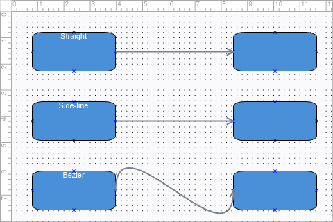
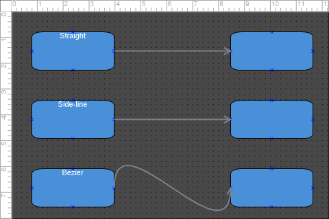
Line styles
LineStyle selects how the path between the endpoints is drawn:
TTMSFNCBloxLineStyle |
Path |
|---|---|
lsLine |
A single straight segment (the default). |
lsSideLine |
Perpendicular (orthogonal) segments — the flowchart "elbow" connector. |
lsParabolicArc |
A parabolic arc. |
lsCircularArc |
A circular arc. |
lsBezier |
A bezier curve. |
procedure TForm1.AddStyledLine(ASource, ATarget: TTMSFNCBloxBlock;
  AStyle: TTMSFNCBloxLineStyle);
var
  LLine: TTMSFNCBloxLine;
begin
  LLine := TTMSFNCBloxLine.Create;
  LLine.LineStyle := AStyle;            { lsLine, lsSideLine, lsCircularArc, lsBezier, ... }
  LLine.SourceLinkPoint.AnchorLink := ASource.LinkPoints[3]; { right }
  LLine.TargetLinkPoint.AnchorLink := ATarget.LinkPoints[2]; { left }
  LLine.TargetArrow.Shape := asLineArrow;
  BloxControl1.Blox.Add(LLine);
end;
Arrows
Each end has an arrow (SourceArrow and TargetArrow, both
TTMSFNCBloxLineArrow). Set Shape to choose the head and Width / Height to
size it:
TTMSFNCBloxArrowShape |
Head |
|---|---|
asNone |
No arrowhead. |
asSolidArrow |
Filled triangle. |
asLineArrow |
Open (line) arrow. |
asDiamond / asAngledDiamond |
Diamond heads. |
asRectangle / asEllipse |
Block and round terminators. |
asHalfLine |
Half-barb. |
Mandatory anchoring and labels
Set RequiresConnections := True to forbid a line whose ends are not both
anchored to a block — the user cannot insert, move, or resize it until it is
fully connected, which keeps flow diagrams valid. A line also carries text:
assign Text for the centre label, or index the TextCells collection for
finer control over the individual cells along the line.
Putting it together
The example below combines a styled side-line, a solid arrow, a centre label, and a required connection in one connector:
function TForm1.AddLabeledConnection(ASource, ATarget: TTMSFNCBloxBlock;
  const ALabel: string): TTMSFNCBloxLine;
begin
  Result := TTMSFNCBloxLine.Create;
  Result.LineStyle := lsSideLine;             { orthogonal elbow connector }
  Result.SourceLinkPoint.AnchorLink := ASource.LinkPoints[1];
  Result.TargetLinkPoint.AnchorLink := ATarget.LinkPoints[0];
  Result.TargetArrow.Shape := asSolidArrow;
  Result.TargetArrow.Width := 14;
  Result.TargetArrow.Height := 14;
  Result.Text := ALabel;                       { label shown at the line centre }
  Result.RequiresConnections := True;          { both ends must stay connected }
  BloxControl1.Blox.Add(Result);
end;
Pitfalls
- Anchoring to a block with no link points fails silently — the endpoint has nothing to attach to. Ensure the block has link points first.
RequiresConnectionsblocks interactive editing of unconnected lines. Set it only after both endpoints are anchored, or the user cannot manipulate the line at all.- Link-point indices are layout-specific. For the default four points the order is top, bottom, left, right (0–3); verify the order for library blocks that define their own.